

I have always been interested in the creation of 3D models. Not so much from the artistic side, but from the technical side of how they are constructed: how mathematics, geometry, and a little visual trickery can convince our brains that we are looking at a three-dimensional object on a flat monitor.
Creating usable 3D models remains expensive and time-consuming. Modern generative systems such as TRELLIS.2, Pixel3D, and similar tools can produce visually impressive results, often by working with implicit or volumetric representations before extracting and processing a final mesh.
However, generating a visually convincing object is not the same as generating a production-ready asset.
The resulting geometry may be polygon-heavy, difficult to edit, or too coarse to preserve important structural details. More importantly, the final mesh does not explain how the object was constructed. It gives you a surface, but not the process that created it.
My work explores a different approach.
Instead of asking an AI model to generate the final geometry directly, I use large language models to generate procedural construction programs. The language model describes the operations required to build an object, and a deterministic 3D runtime executes those operations.
(part
(input base_width 50.5)
(input base_depth 29)
(input base_height 15)
(box id base_rect width base_width depth base_depth height base_height)
(place base_rect.bottom on grid.xy offset x -7.25)
(cylinder id base_round radius (/ base_depth 2) height base_height)
(place base_round.bottom on grid.xy offset x 18)
(union into base_rect base_round)
(box id upright width 30 depth base_depth height 62)
(place upright.bottom on grid.xy offset x -17.5)
(union into base_rect upright)
(output body base_rect))
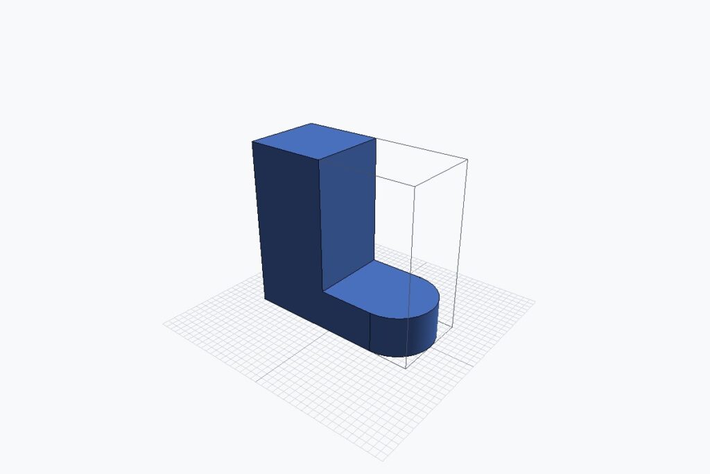
Simple example from my engineering-parts DSL
The language model is therefore not the geometry engine. Its role is to interpret the request, select or generate a construction process, and express that process using a constrained language. The runtime remains responsible for producing the actual geometry.
This changes the problem from generating a finished mesh to generating the process used to build it.
When the construction process is represented explicitly, the resulting model becomes easier to inspect, modify, reproduce, and verify. Dimensions can be changed. Parts can be repositioned. Variations can be produced without rebuilding the object from scratch. Errors can be traced back to specific construction operations rather than hidden inside an opaque mesh.
(part
(input base_width 50.5)
(input base_depth 50)
(input base_height 15)
(box id base_rect width base_width depth base_depth height base_height)
(place base_rect.bottom on grid.xy offset x -7.25)
(cylinder id base_round radius (/ base_depth 2) height base_height)
(place base_round.bottom on grid.xy offset x 18)
(union into base_rect base_round)
(box id upright width 30 depth base_depth height 62)
(place upright.bottom on grid.xy offset x -17.5)
(union into base_rect upright)
(output body base_rect))
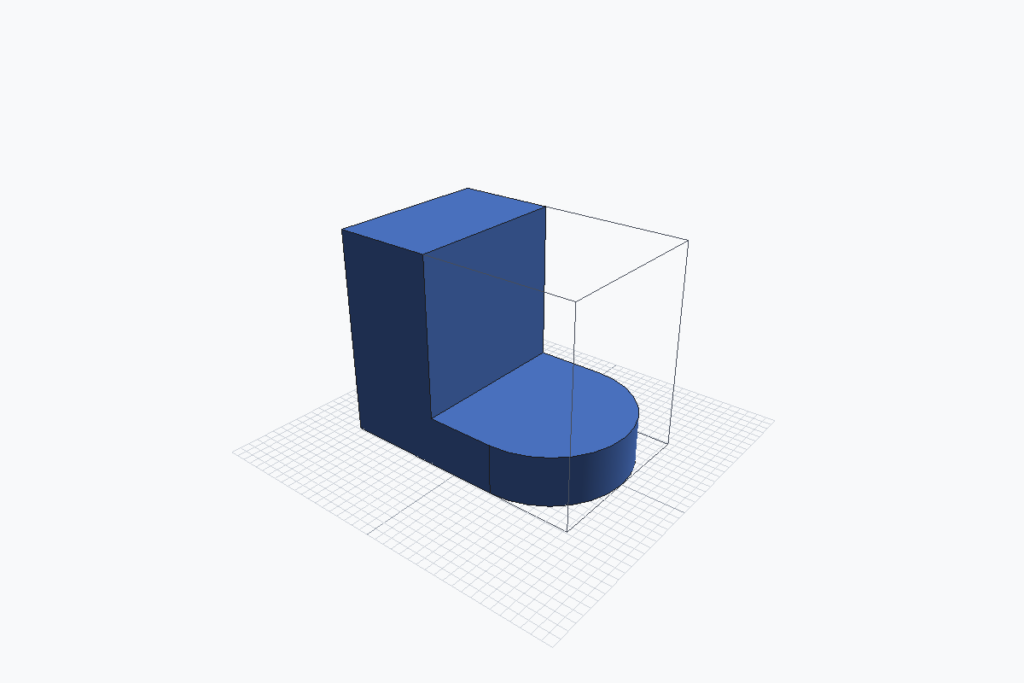
Example of making a variation by changing a parameter (base_depth) from my engineering-parts DSL
I have been working on variations of this problem for the past three years. During that time, the work has evolved through three related projects.
The first two were developed for the company where I currently work and focus on the generation of assets for Digital Twin applications. The third is a personal project with a different objective: generating precise mechanical and engineering parts.
The connection between the three projects is not a shared product or codebase. It is the same underlying architectural idea: use AI to generate an explicit construction process, and use deterministic software to turn that process into geometry.
Starting with Known Templates
The first system I built uses a library of manually created procedural templates.
The library can generate around 200 categories of objects, including chairs, trees, street furniture, and other assets commonly required in Digital Twin environments. Each template contains the construction logic for a category of object and exposes a set of parameters that control the result.
Simple assets may have only four or five parameters. More complex assets, such as trees, may expose 20 or more.
The templates are indexed through a retrieval-augmented generation system. Given a text prompt, the language model searches the library, selects the most suitable template, and generates the parameters required to produce the requested asset. The pipeline also uses AI for reranking retrieved results and can accept image input to infer parameters from a visual reference.

For example, the system does not need to generate the geometry of a chair from nothing. It retrieves a suitable chair template and determines values such as its width, height, proportions, structural variation, leg placement, and other construction details.
Starting with templates was a deliberate reduction in scope.
Before attempting to generate arbitrary construction logic, we could first validate whether a language model could identify an appropriate object category, select a known procedure, and infer useful parameters from text or images. This gave us a constrained environment in which the geometry generation itself remained predictable.
The approach works reliably when the requested object fits an existing structural category. It becomes less reliable when a prompt combines characteristics that belong to several templates or asks for an object that the library does not support.
That limitation is fundamental. The system can only generate categories for which a suitable template already exists. Expanding its capabilities requires creating additional procedural templates by hand, and designing a good template takes a significant amount of time.
The advantage of the template system is speed. Because an existing procedure only needs a new set of parameters, variations can be generated in seconds.
The first system solved the problem of selecting a known construction method and configuring it. The next challenge was to generate the construction method itself.
Why Python Was Not Enough
Before creating a dedicated language, we experimented with unrestricted Python generation.
It worked surprisingly well for simple objects. A language model could write scripts that created primitives, transformed them, and combined them into basic shapes.
However, Python was not designed specifically for procedural 3D generation by language models. It was too verbose, and the amount of code required increased quickly as objects became more complex.
More importantly, Python scripts and conventional 3D APIs are not designed around verification and progressive refinement.
A general-purpose script can produce geometry, but it does not necessarily expose the relationships the model needs to understand in order to revise that geometry safely. The model may know that one box is a chair seat and another is a backrest, but those concepts are not naturally represented by a sequence of low-level transformations and API calls.
We repeatedly observed several problems.
The generated scripts could be spatially incoherent even when the code appeared plausible. Absolute coordinates were difficult to maintain across revisions. A change to one part could require manually recalculating the positions of several others. Scripts also tended to lose consistency as the model added or changed details over multiple iterations.
Most generated assets still require some degree of manual correction. To make that process more useful, we developed a tool that allows 3D artists to annotate issues directly on a generated asset and ask the agent to apply targeted fixes.
Designing a Language for Construction
To address these limitations, I created a domain-specific language for procedural 3D modeling.
The objective was not merely to replace Python with shorter syntax. The language was designed around the concepts that language models need to express and revise construction processes effectively.
The two most important concepts are relationships and composition.
Instead of relying primarily on absolute coordinates, the language allows parts to be positioned relative to other parts. A backrest can be attached to the rear edge of a seat. Legs can be distributed beneath its corners. A handle can be aligned with the centre of a door.
(part
(input top_width 4.0)
(input top_depth 2.4)
(input top_height 0.28)
(input rounding_radius 0.12)
(input leg_width 0.22)
(input leg_height 2.4)
(box id tabletop width top_width depth top_depth height top_height side_fillet_radius rounding_radius
(fillet select top radius 0.025)
(fillet select bottom radius 0.015))
(import “leg.part” prefix leg_ width leg_width
height leg_height rounding_radius rounding_radius)
(place leg_top on tabletop.bottom id fl_leg_placed
offset x (* -0.5 (- top_width leg_width))
y (* -0.5 (- top_depth leg_width)))
(rotate leg_body id fr_leg axis z angle 90 center 0 0 0)
(place fr_leg.top on tabletop.bottom id fr_leg_placed
offset x (* 0.5 (- top_width leg_width))
y (* -0.5 (- top_depth leg_width)))
(rotate leg_body id bl_leg axis z angle 270 center 0 0 0)
(place bl_leg.top on tabletop.bottom id bl_leg_placed
offset x (* -0.5 (- top_width leg_width))
y (* 0.5 (- top_depth leg_width)))
(rotate leg_body id br_leg axis z angle 180 center 0 0 0)
(place br_leg.top on tabletop.bottom id br_leg_placed
offset x (* 0.5 (- top_width leg_width))
y (* 0.5 (- top_depth leg_width)))
(union id table_raw tabletop fl_leg_placed fr_leg_placed bl_leg_placed br_leg_placed)
(place table_raw.bottom on grid.xy id table)
(output body table))
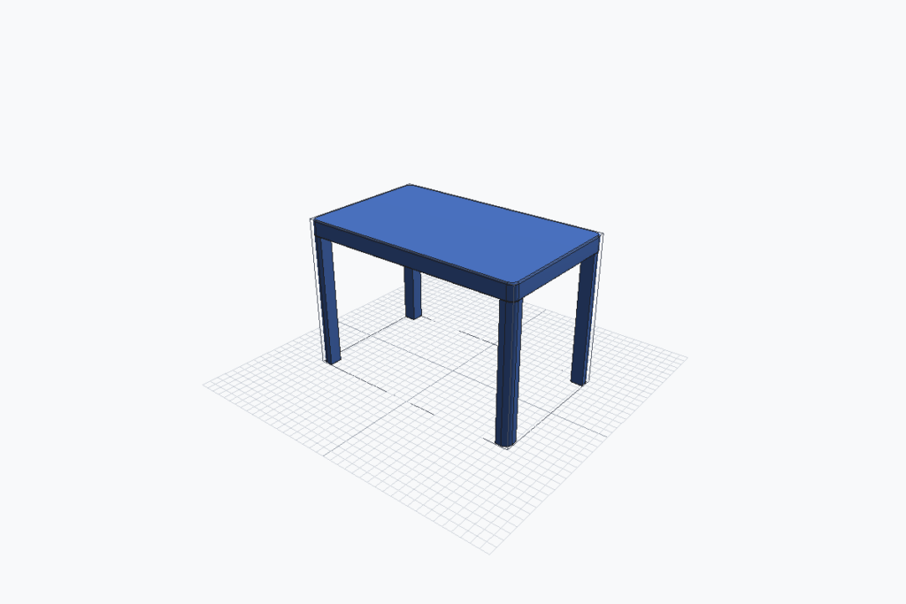
Positioning and compositing example from my engineering-parts DSL
This relational representation makes revisions more stable. If the dimensions of the seat change, the positions of the attached components can be recalculated by the runtime rather than regenerated independently by the language model.
Composition is equally important.
Complex assets should not be treated as a single undifferentiated shape. They should be constructed from smaller components that can be generated, positioned, reused, and refined separately.
In practice, this remains one of the harder behaviors to obtain from a general-purpose language model. Unless composition is explicitly requested, the model often prefers a simpler construction using fewer operations. It produces a recognizable object, but not necessarily the level of detail or modularity that we want.
Fine-tuning the model to prefer composition and make better use of the available language features is one of my current priorities.
Generating New Assets
An agentic system can use the DSL to plan an object, generate its construction operations, execute them, inspect the result, and propose revisions.
This moves the system beyond selecting from a fixed library. It allows the model to generate a new procedural definition for an object that was not previously supported.
Generating a new asset usually takes minutes rather than seconds because the system has to create and refine the construction program. Corrections can also often be produced within minutes by modifying the relevant part of the DSL rather than regenerating the entire object.
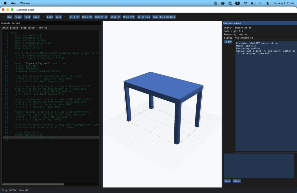
Screen capture of Step, one of the tools I have implemented for my engineering-parts DSL
The quality is not yet uniform across every category. In principle, the system can attempt a much wider range of objects than the template-based system, but some categories are generated more successfully than others.
The current verification process remains heavily human-in-the-loop.
The agent can inspect the DSL representation, render the generated asset, compare those renders with reference images, and evaluate geometric measurements, topology, and semantic assertions. However, identifying the exact operation that introduced an error is still usually performed with human guidance.
We also use rendered-image divergence and semantic divergence to identify differences between the generated result and the reference. Some checks are deterministic, but many still rely on language or vision models to identify discrepancies.
Preventing refinement loops from making the result worse is another important challenge. We currently control this through human review, deterministic execution, and the ability to revert changes easily.
This is one of the benefits of representing the model as a construction program. A revision may introduce an incorrect detail, but the change is explicit and can be corrected or reverted. The underlying object does not gradually degrade through a series of opaque mesh modifications.
Why Digital Twins Need More Than a Mesh
The second system is being developed for Digital Twin applications, where large numbers of structured and reusable assets may be required.
In this context, visual similarity is not enough.
An asset may need to move, interact with other objects, respond to simulation events, or expose configurable parameters. It may require colliders, interaction points, animation states, semantic metadata, or replaceable components.
Because the assets are generated procedurally, these properties can be included as part of their construction rather than added manually afterward.
A generated door can contain the axis around which it rotates. A machine can identify the components that move. A storage unit can be regenerated at different dimensions while preserving its internal relationships. The asset becomes more than a static surface. It becomes a configurable component of the simulation.
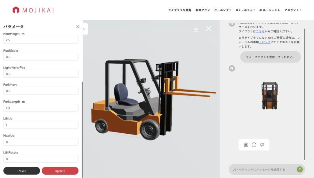
An adjustable forklift for hazardous-environment scenarios in digital twin simulations
We have used generated assets in real Digital Twin environments, including assets derived from GIS data and building blueprints.
In this type of workflow, the real bottleneck is not generating one attractive model. It is generating large numbers of consistent assets that remain editable, configurable, and semantically meaningful after they have been placed inside a simulation.
A procedural representation is particularly valuable because it preserves that structure.
Applying the Same Idea to Engineering Parts
In my spare time, I am applying the same architectural idea to a more demanding domain: mechanical and engineering geometry.
This is a personal project, separate from the two Digital Twin systems, and it has a different objective.
Rather than generating simulation assets, this system generates engineering parts using a second domain-specific language. It uses Open CASCADE Technology, or OCCT, as its geometric backend and includes custom geometry kernels for operations such as sheet-metal bending and accurate thread generation.
(part
(input blank_width 4.0)
(input blank_depth 3.4)
(input bend_line_y 0.5)
(input thickness 0.12)
(input bend_radius 0.18)
(input k_factor 0.44)
(sheet_base id bracket
width blank_width
depth blank_depth
thickness thickness
(sheet_bend
axis x
at bend_line_y
side positive
angle 90
bend_radius bend_radius
k_factor k_factor))
(place bracket.bottom on grid.xy)
(output body bracket))
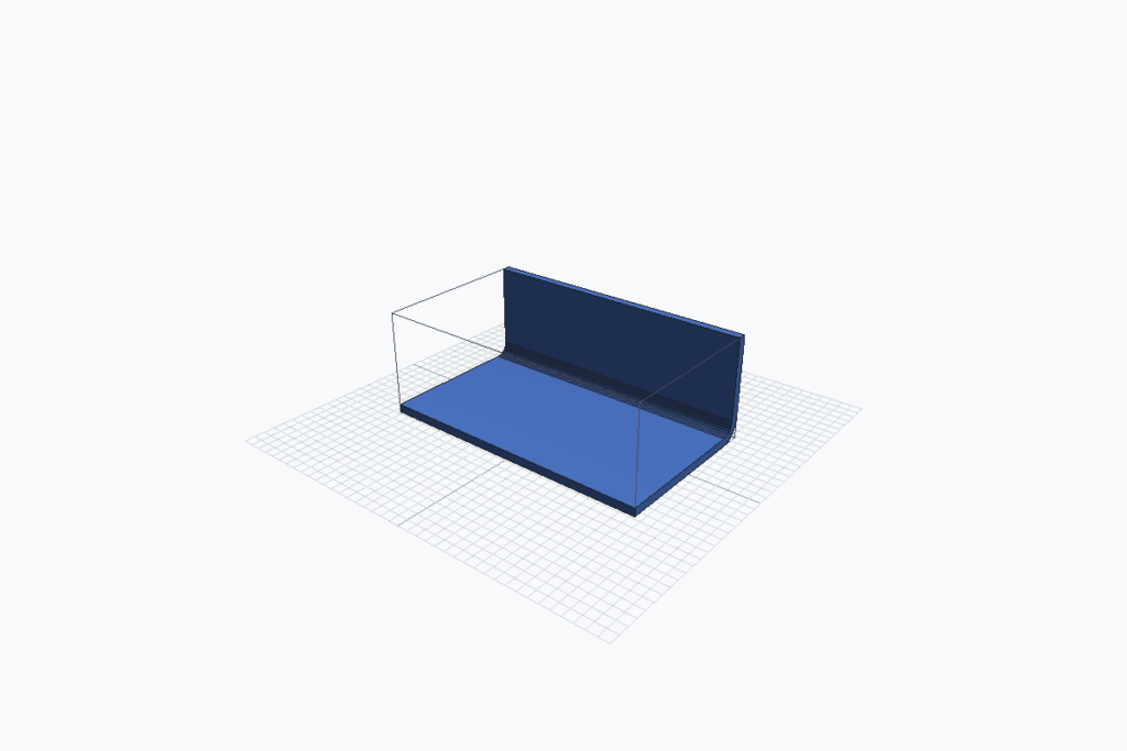
The engineering-parts DSL supports sheet-metal blanks, bends, flanges, and tabs
Engineering geometry introduces much stricter requirements than visual 3D content.
A component cannot merely look correct from a distance. Its dimensions, surfaces, intersections, tolerances, and construction operations need to be precise. A visually plausible part may still be completely unusable if a hole is misaligned, a thread is incorrect, or two surfaces do not intersect as expected.
The engineering DSL therefore represents a part as a sequence of explicit and verifiable CAD operations. These can include sketches, extrusions, cuts, fillets, bends, threads, assemblies, and other operations found in conventional engineering workflows.
The language model generates the DSL. The deterministic runtime interprets it and creates the final part.
(part
(import “bolt.part” prefix bolt_
head_type hex
head_hole_type hex_socket
head_size 1.02
head_height 0.32
head_hole_size 0.34
head_hole_depth 0.13
body_size 0.38
body_length 1.42
thread_size 0.52
thread_length 0.90
thread_screw_size 0.060
thread_screw_interval 0.160)
(place bolt_bottom on grid.xy id threaded_bolt)
(output body threaded_bolt))
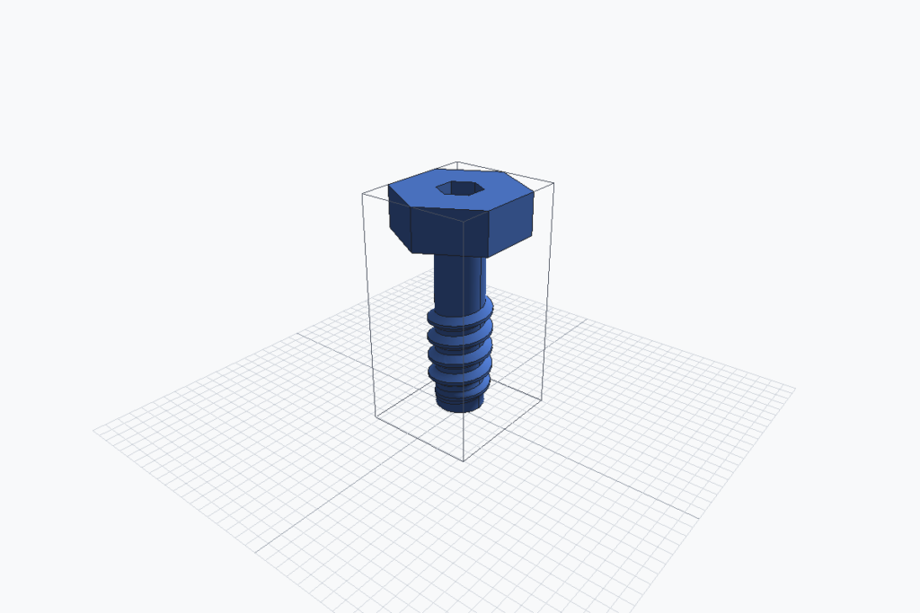
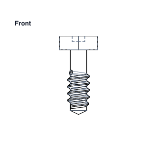
The engineering-parts DSL can generate accurate threaded geometry
Around this DSL, I am building tools using the Odin programming language that compile the generated parts into 3D data that can be exported to formats such as STEP. I am also developing an AI-assisted coding editor for creating, inspecting, and refining the construction programs.
The broader pipeline uses AI in several additional places. For example, it can process engineering blueprints and search for diagrams that may be useful during verification.
Human review remains part of the process. For the engineering system, I am also implementing a view-matching process that compares rendered top, front, side, and other orthographic views against reference drawings.
The system can evaluate structural divergence and semantic drift between the requested and generated parts. Rendered views, geometric measurements, topology checks, and semantic assertions can all contribute to validation.
However, reliable automated verification is still one of the most difficult parts of the project. Many discrepancies can be detected, but tracing them back to the exact operation that caused them often requires human involvement.
The objective is not to have AI produce an opaque final shape. It is to help produce a clear and editable construction program that generates engineering-grade geometry.
Generating the Process
Across these projects, the underlying principle is the same.
The first system generates parameters for human-authored procedures. The second generates new procedures for digital twin assets. The third applies the same idea to engineering parts, where precision, construction history, and verification are essential.
Each stage gives the language model more responsibility, but the architectural boundary remains consistent: the AI interprets intent and generates a constrained construction program; the deterministic runtime executes that program and produces the geometry; verification systems and human reviewers inspect the result and feed corrections back into the process.
This separation matters because language models are probabilistic, while geometry generation needs to be repeatable.
Many difficult problems remain. Language models need to reason more reliably about space, topology, constraints, and sequences of operations. They need to use composition without being explicitly prompted, make better use of the available modeling operations, and recognize when a result is incorrect. Just as importantly, they need to identify which part of the construction process caused the error.
Automated verification is especially challenging. Image comparisons and semantic evaluation can identify many visible differences, but geometry is not only visual. A system also needs to understand dimensions, connectivity, topology, mechanical relationships, and construction intent.
For many practical applications, the important result is not a visually convincing mesh produced in a single step. It is a structured model that can be inspected, modified, verified, and integrated into a larger system.
I believe the future of AI-generated 3D depends less on models that directly predict every surface, and more on systems that can understand and generate the processes from which those surfaces are built.